3422
HALL-EFFECT,
DIRECTION-DETECTION
SENSOR IC
www.allegromicro.com
3
s
t
i
m
i
L
s
t
i
n
U
.
x
a
M
.
p
y
T
.
n
i
M
s
n
o
i
t
i
d
n
o
C
t
s
e
T
l
o
b
m
y
S
c
i
t
s
i
r
e
t
c
a
r
a
h
C
Supply Voltage Range
V
CC
Operating, T
J
< 165癈
1
4.5 18 V
Output Leakage Current
I
OFF
V
OUT
= V
CC
0
1
0
.
1
<
V
8
1
=
糀
Output Saturation Voltage V
OUT(SAT)
I
OUT
V
0
5
.
0
1
2
.
0
A
m
0
2
=
Power-On State
POS V
CC
= 0 ?/DIV>
F
F
O
F
F
O
F
F
O
,
V
5
B
RP1
< B < B
OP1
, B
RP2
< B < B
OP2
Undervoltage Lockout
V
CC(UV)
I
OUT
= 20 mA, V
CC
= 0 ?5 V
3.5 V
Undervoltage Hysteresis V
CC(hys)
Lockout (V
CC(UV)
) - Shutdown
0.5 V
Power-On Time
t
po
V
CC
0
5
V
5
.
4
>
約
Output Rise Time
t
r
C
L
= 20 pF, R
L
= 820
200 ns
Output Fall Time
t
f
C
L
= 20 pF, R
L
= 820
200 ns
Direction Change Delay
t
d
C
L
= 20 pF, R
L
= 820
0.5 1.0 5.0 約
Supply Current
I
CC
V
CC
= 8 V, All outputs OFF
5.0 9.0 18 mA
ELECTRICAL CHARACTERISTICS over operating temperature range.
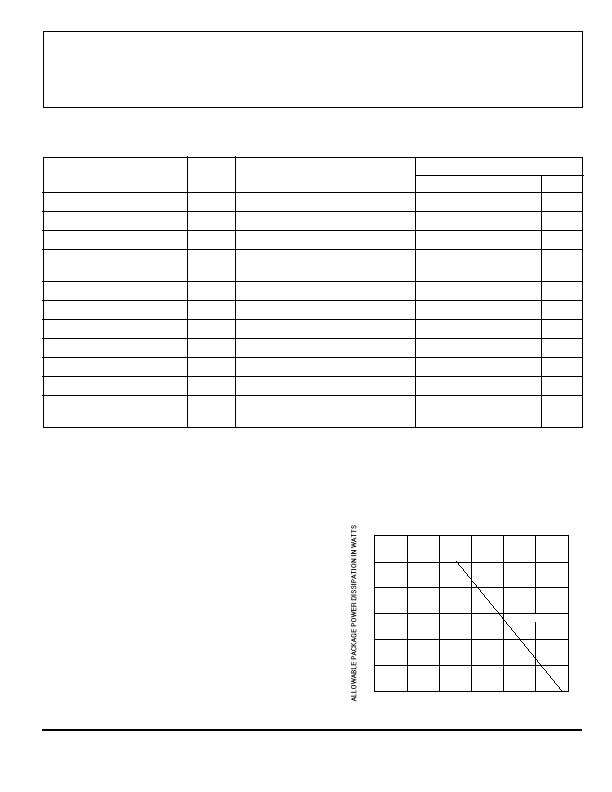
NOTES: 1. Maximum supply voltage must be adjusted for power dissipation and ambient temperature.
2. Typical Data is at V
CC
= 12 V and T
A
= +25癈 and is for design information only.
50
75
100
125
175
0.5
0.1
0
TEMPERATURE IN 癈
0.4
0.3
0.2
25
Dwg. GH-069
R?SPAN class="pst A3422LKA-T_2596293_8">JA = 164癈/W
0.6
150
发布紧急采购,3分钟左右您将得到回复。
相关PDF资料
AAH002-02
SENSORS MAGNETIC FIELD 8SOIC
AD221-00
SENS MAG SW 20G CROS AXIS 8-MSOP
ADH025-00
SENSOR MAG SW 10G CRS AXS 8-MSOP
ADL024-14E
DIGITAL SWITCH 55HZ ULLGA
AFL300-00
SWITCH MAGNETIC DIG 5.5V 8MSOP
AH173-WL-7-A
IC HALL SENSOR LATCH 25MA SC59-3
AH175-PL-B-B
IC HALL SENSOR BIPO LATCH SIP-3L
AH1751-PG-A-A
IC HALL SENSOR LATCH SIP-3
相关代理商/技术参数
A3422XKA
制造商:未知厂家 制造商全称:未知厂家 功能描述:HALL-EFFECT. DIRECTION-DETECTION SENSORS
A3423EK-T
功能描述:IC DIRECTION SENSOR 2CH 4-SIP RoHS:是 类别:传感器,转换器 >> 磁性 - 霍尔效应,数字式开关,线性,罗盘 (IC) 系列:- 标准包装:1 系列:- 传感范围:20mT ~ 80mT 类型:旋转 电源电压:4.5 V ~ 5.5 V 电流 - 电源:15mA 电流 - 输出(最大):- 输出类型:数字式,PWM,8.5 位串行 特点:可编程 工作温度:-40°C ~ 150°C 封装/外壳:20-SSOP(0.209",5.30mm 宽) 供应商设备封装:20-SSOP 包装:Digi-Reel® 其它名称:AS5132-HSST-500DKR
A3423ELTR-T
功能描述:IC DIRECTION DETECT SENSOR 8SOIC RoHS:是 类别:传感器,转换器 >> 磁性 - 霍尔效应,数字式开关,线性,罗盘 (IC) 系列:- 标准包装:1 系列:- 传感范围:20mT ~ 80mT 类型:旋转 电源电压:4.5 V ~ 5.5 V 电流 - 电源:15mA 电流 - 输出(最大):- 输出类型:数字式,PWM,8.5 位串行 特点:可编程 工作温度:-40°C ~ 150°C 封装/外壳:20-SSOP(0.209",5.30mm 宽) 供应商设备封装:20-SSOP 包装:Digi-Reel® 其它名称:AS5132-HSST-500DKR
A3423LK-T
功能描述:IC DIRECTION SENSOR 2CH 4-SIP RoHS:是 类别:传感器,转换器 >> 磁性 - 霍尔效应,数字式开关,线性,罗盘 (IC) 系列:- 标准包装:1 系列:- 传感范围:20mT ~ 80mT 类型:旋转 电源电压:4.5 V ~ 5.5 V 电流 - 电源:15mA 电流 - 输出(最大):- 输出类型:数字式,PWM,8.5 位串行 特点:可编程 工作温度:-40°C ~ 150°C 封装/外壳:20-SSOP(0.209",5.30mm 宽) 供应商设备封装:20-SSOP 包装:Digi-Reel® 其它名称:AS5132-HSST-500DKR
A3423LLTR-T
功能描述:IC DIRECTION DETECT SENSOR 8SOIC RoHS:是 类别:传感器,转换器 >> 磁性 - 霍尔效应,数字式开关,线性,罗盘 (IC) 系列:- 标准包装:1 系列:- 传感范围:20mT ~ 80mT 类型:旋转 电源电压:4.5 V ~ 5.5 V 电流 - 电源:15mA 电流 - 输出(最大):- 输出类型:数字式,PWM,8.5 位串行 特点:可编程 工作温度:-40°C ~ 150°C 封装/外壳:20-SSOP(0.209",5.30mm 宽) 供应商设备封装:20-SSOP 包装:Digi-Reel® 其它名称:AS5132-HSST-500DKR
A3425
制造商:ALLEGRO 制造商全称:Allegro MicroSystems 功能描述:DUAL, CHOPPER-STABILIZED, ULTRA-SENSITIVE, BIPOLAR HALL-EFFECT SWITCH
A3425_06
制造商:ALLEGRO 制造商全称:Allegro MicroSystems 功能描述:Ultra-Sensitive Dual-Channel Quadrature Hall-Effect Bipolar Switch
A3425EK
制造商:ALLEGRO 制造商全称:Allegro MicroSystems 功能描述:Ultra-Sensitive Dual-Channel Quadrature Hall-Effect Bipolar Switch